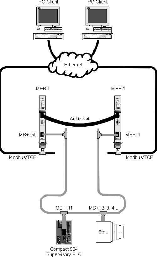
Figure 1: Physical connection of the MEBs to Ethernet and Modbus Plus.
 Hot standby MEB-TCPs
Topic: MEB-TCPs in hot standby operation
Product: MEB-TCP
Author: Chas. Adam Crowder
Two MEB-TCPs can provide "hot standby" connectivity from an Ethernet network to PLCs and other devices on a Modbus Plus (MB+) network, such that a single IP address will always access a "healthy" MEB-TCP. In the event the primary MEB-TCP loses communications or power, the secondary MEB-TCP will assume the IP address assigned to the primary MEB-TCP. Within 2 seconds (adjustable) of the primary losing communications, the secondary will be online at its IP address.
NOTE: Some SCADA/HMI packages now support primary and secondary IP addresses and destination indices for their connection to Modbus/TCP devices. This is a much better solution, as it enables a system to divide its traffic between both bridges while they're both functioning.
This application note describes the use of two NR&D MEB Modbus Plus to Ethernet bridges to provide a redundant link from an Ethernet network to a Modbus Plus (MB+) network (See Figure 1). The MEBs in this application are continuously online, each with a functional IP address and independent connections to the Ethernet and MB+ networks.
A supervisory PLC on the MB+ network (a Compact 984-145, in this application) continuously monitors both MEBs' MB+ and Ethernet connections, and swaps their IP addresses when the primary MEB loses any of its communications links. Any time either MEB has lost either its MB+ or Ethernet communications, the supervisory PLC activates an output for an alarm.
This application assumes that the critical traffic through the MEBs is from Ethernet to MB+. This allows the MEBs' MB+ addresses to remain unchanged. In the event that the traffic is two-way, the application could easily be modified to swap the MEBs' MB+ addresses, but this would cause the MEBs' MB+ ports to be offline for 10 seconds as their MB+ chipsets reboot.
It is also assumed that at least one Modbus/TCP client will always have a connection to the primary MEB. The supervisory PLC uses the "open connection count" statistic of the primary MEB to validate its Ethernet health. If no client is connected to the primary MEB, the supervisory PLC will assume it is not connected to the Ethernet, and swap the MEBs' IP addresses every 20 seconds (as the application below is written) until a Modbus/TCP connection is made to the primary MEB.
This application requires two MEB-TCPs to be independently connected to both the Ethernet and MB+ networks (see Figure 1, below). The MEBs must also be connected serially, using the Net-to-Net protocol. This serial connection provides the supervisory PLC a second path to the primary MEB should its MB+ connection fail. Separate connections to Ethernet, and separate connections to the MB+ network reduce the possibility of a single hardware failure foundering both MEBs.
The supervisory PLC monitors the "health" of the primary MEB by periodically (the ladder logic below checks every two seconds) polling it directly via MB+. This "health check" read reads register 2061 in the primary MEB (See Network 4, below). Register 2061 is a statistic register in the MEB which indicates how many IP connections are currently open to the MEB.
NOTE: The "Quiet Timeout" parameter must be adjusted on both MEBs for this application. The default Quiet Timeout is 600 (seconds) for an MEB. A Quiet Timeout of 5 was used in this application. This parameter indicates how long the MEB will keep a quiet (i.e. no reads or writes) IP connection open without validating its connection to the master. In the event the primary MEB's Ethernet connection fails, all of its connections will close after the quiet timeout expires, triggering the supervisory PLC to effect the MEB changeover.
Two things will trigger the secondary MEB to change over to the primary IP address:
The following steps are taken to effect the changeover of IP addresses:
Because the new primary MEB will have no TCP connections immediately after an IP address change, the periodic health checks must be disabled immediately after a changeover. The timer in Network 14 keeps the health check from happening for 20 seconds after a changeover is started. This delay gives the Ethernet devices a chance to reestablish a connection to the MEB before the health checking resumes. This timer starts the instant a changeover begins, and allows health checking to resume after the timer expires. Thus, if no TCP connections are established to the primary MEB, this timer will allow their IP addresses to swap once every 20 seconds until a connection is made to the primary.
NOTE: By default, ARP entries in most PCs are maintained for 20 seconds. As such, a PC may take 20 seconds to clear its ARP entry for the primary MEB's IP address and establish communication with the new primary.
Network 15 sets up, and Network 16 executes a read which routes out the primary MEB, across Ethernet to the secondary MEB, then via MB+ back to the supervisory PLC. If everything is in proper working order, this read should complete successfully, but if either MEB is missing either network connection, this read will fail. In this application, any failure of this read sets coil 0x0001 as an alarm output. The coil remains set until this circular read completes successfully.
Following are the important configuration parameters for the MEBs in this system. Parameters not addressed were left at factory default, or are not important to the application.
|
| ||||||||||||||||||||||||||||||||||||||||||||||||||||||||||||||||||||
Figure 1: Physical connection of the MEBs to Ethernet and Modbus Plus.
Segment: 01 Network:0001
Sets MBP Address of MEB1, MEB2
This puts the Modbus Plus addresses of the MEBs into registers
41002 and 41003
1+--------------------+
| |
| |
2+-------+----+- ++----+-
| #0050| #0001|
| | | | |
3+ | | | |
| #0000| #0000|
| | | | |
4+ |ADD | |ADD |
| 41002| 41003|
| +----+ +----+
Segment: 01 Network:0002
Timer rung for Health Check
Fires coil 1000 every 2 seconds unless register 1004 is activated
(indicating that a changeover is in progress)
1+----------------------------------------------------------+/+--+----+----( )
| 01004 #0020| 01000
| | |
2+----------------------------------------------------------+/+--+T0.1+-
| 01000 41001|
| +----+
3+
|
|
4+--+ +-+
|01003 |
| |
5+--+/+-+
|01011 |
| |
6+ |
7+ +--------------------------------------------- - - - - - - - - --( )
| 01004
|
Segment: 01 Network:0003
Routing Setup for Health Check
Sets up the MSTR data block such that a read of register 2061 is issued
and the results are placed in 41020. This value which is read is the
number of active TCP connections open to the primary MEB.
1+--+ +-+-------------+-------------+-------------+
|01000 | | | |
| | | | |
2+ ++----+- ++----+- ++----+- ++----+-
| #0000| #0000| #0900| #0261|
| | | | | | | | |
3+ | | | | | | | |
| #0002| #0001| #0900| 41103|
| | | | | | | | |
4+ |ADD | |ADD | |ADD | |ADD |
| 41100| 41102| 41103| 41103|
| +----+ +----+ +----+ +----+
Segment: 01 Network:0004
Health check on Primary MEB
MSTR reads the MEB when coil 1000 toggles.
Coil 1013 is latched on when one Health check read has completed
successfully.
1+--+ +---------------+------+------------------------ - - - - - - - - --( )
|01000 | | 01001
| | |
2+--+ +----+/+----+/+-+ ++----+-
|01001 01002 01012 41100|
| | |
3+ + +---- - - - - - - - - - - - - - - - --( )
| 41020| 01002
| | |
4+ |MSTR+---- - - - - - - - - - - - - - - - --( )
| #0001| 01012
| +----+
5+--+ +----+/+------------------------------------+------------------------( )
|01013 01003 | 01013
| |
6+--------------------------------------------+ +-+
| 01012
|
Segment: 01 Network:0005
Determine changeover necessity
If the health check MSTR returns an error, or if the read completes
successfully but the value read is zero, then latch on coil 1003, which
starts the process of swapping the primary and secondary.
1+--+ +----------------------+
|01002 |
| |
2+--+ +---------+----+- |
|01013 41020| |
| | | |
3+ | +-------+--+/+----+ +---------------------------------( )
| #0000| |01006 01011 01003
| | | |
4+ |SUB +- |
| 41006| |
| +----+ |
5+--+ +----------------------+
|01003
|
Segment: 01 Network:0006
Determine what routes to write
Sets coil 1005 if MEB1 was primary.
Register 41006 is not used anywhere; the subtract (which is only being used
as a compare) will not operate without a register address in the bottom
node.
1+
|
|
2+--+ +--+----+-
|01003 41002|
| | |
3+ | +--- - - - - - - - - - - - - - - - - - - - - - - - - - - --( )
| 41104| 01005
| | |
4+ |SUB +-
| 41006|
| +----+
Segment: 01 Network:0007
Make MEB1 Primary
This network writes a route of MEB1.3.0.0.0 to the MSTR block at 41100
and a route of MEB1.1.0.0.0 to the MSTR block at 41110
The first route is the route to the Primary MEB, and the second route is
the route to the secondary MEB, thru the Net-to-Net connection on port 1
1+--+ +----+ +--------+-------------+
|01003 01005 | |
| | |
2+ ++----+- ++----+-
| |41003| |#0003|
| || | || |
3+ || | || |
| |#0000| |#0000|
| || | || |
4+ ||ADD | ||ADD |
| |41104| |41105|
| |+----+ |+----+
5+ ++----+- ++----+-
| 41003| #0001|
| | | | |
6+ | | | |
| #0000| #0000|
| | | | |
7+ |ADD | |ADD |
| 41114| 41115|
| +----+ +----+
Segment: 01 Network:0008
Make MEB2 Primary
Same as the previous network, except that these make MEB2 primary...
1+--+ +----+/+--------+-------------+
|01003 01005 | |
| | |
2+ ++----+- ++----+-
| |41002| |#0003|
| || | || |
3+ || | || |
| |#0000| |#0000|
| || | || |
4+ ||ADD | ||ADD |
| |41104| |41105|
| |+----+ |+----+
5+ ++----+- ++----+-
| 41002| #0001|
| | | | |
6+ | | | |
| #0000| #0000|
| | | | |
7+ |ADD | |ADD |
| 41114| 41115|
| +----+ +----+
Segment: 01 Network:0009
Trigger next stages
Coil 1003 triggers coils 1006 and 1007, which start the writes to set the IP
addresses of the Secondary and Primary MEBs, respectively.
Coil 1006 is latched on until its MSTR completes successfully.
Coil 1007 is latched on until its MSTR completes successfully.
1+--+ +-+---------+/+------------------------------------------------------( )
|01003 | 01008 01006
| |
2+--+ +-+
|01006
|
3+
|
|
4+--+ +-+---------+/+------------------------------------------------------( )
|01003 | 01009 01007
| |
5+--+ +-+
|01007
|
Segment: 01 Network:0010
MSTR setup for IP address write
Sets up the MSTR block to write 2 registers to register 2900 and 2901 in the
MEB (IP address)
1+--+ +-+-------------+-------------+-------------+
|01006 | | | |
| | | | |
2+ ++----+- ++----+- ++----+- ++----+-
| #0001| #0002| #0975| #0950|
| | | | | | | | |
3+ | | | | | | | |
| #0000| #0000| #0975| 41113|
| | | | | | | | |
4+ |ADD | |ADD | |ADD | |ADD |
| 41110| 41112| 41113| 41113|
| +----+ +----+ +----+ +----+
Segment: 01 Network:0011
MSTR to set 2ry IP address
MSTR is latched on (repeating failed writes as fast as possible) until
a successful write sets the IP address of the secondary.
The IP address which is written to the secondary is not set anywhere in
the ladder code, since it is such a pain in the ass to assign a value greater
than 999 to a register in this compact 984. Maybe there is an easier way.
1+
|
|
2+--+ +---------+----+-
|01006 41110|
| | |
3+ + +-
| 41007|
| | |
4+ |MSTR+---- - - - - - - - - - - - - - - - - - - - - - - --( )
| #0002| 01008
| +----+
Segment: 01 Network:0012
Setup MSTR block: primary IP wrt
Set up MSTR block for writing 2 registers to register 2900 and 2901 in the
primary MEB, to set its IP address.
1+--+ +-+-------------+-------------+-------------+
|01007 | | | |
| | | | |
2+ ++----+- ++----+- ++----+- ++----+-
| #0001| #0002| #0975| #0950|
| | | | | | | | |
3+ | | | | | | | |
| #0000| #0000| #0975| 41103|
| | | | | | | | |
4+ |ADD | |ADD | |ADD | |ADD |
| 41100| 41102| 41103| 41103|
| +----+ +----+ +----+ +----+
Segment: 01 Network:0013
Write IP address to primary
Repeats write, ad infinitum, until a successful completion.
The IP address which is written must be manually entered. See note in
the "Write IP address to secondary" network
1+
|
|
2+--+ +---------+----+-
|01007 41100|
| | |
3+ + +-
| 41004|
| | |
4+ |MSTR+---- - - - - - - - - - - - - - - - - - - - - - - --( )
| #0002| 01009
| +----+
Segment: 01 Network:0014
Hold off Health Check
This timer holds off the health checking after a changeover is effected
in order to allow the Modbus/TCP client to establish connections to the
new Primary.
1+--+ +-+
|01003 |
| |
2+--+ +-+-------+----+---- - - - - - - - - - - - - - - - - - - - - - - --( )
|01010 #0020| 01011
| | |
3+--+/+---------+T1.0+---- - - - - - - - - - - - - - - - - - - - - - - --( )
|01003 41009| 01010
| +----+
Segment: 01 Network:0015
Set up Full Circle Read Route
This sets up a route of [Primary].4.63.11.0 in the MSTR block at 41120.
This route goes through the primary MEB, over Modbus/TCP to the secondary,
over MB+ back to this PLC. If this read does not complete, an alarm will
sound, assuming that you would want to know if your backup was offline...
This route assumes that entry number 63 in both MEBs TCP lookup tables
contains the IP address of the secondary MEB, and that the Modbus Route
number 11 (again, in both MEBs) points to the PLC controlling this operation,
or some other working MB+ device.
1+------+-------------+-------------+-------------+-------------+
| | | | | |
| | | | | |
2+ ++----+- ++----+- ++----+- ++----+- ++----+-
| |#0002| |#0001| |#0001| 41104| #0004|
| || | || | || | | | | |
3+ || | || | || | | | | |
| |#0000| |#0000| |#0000| #0000| #0000|
| || | || | || | | | | |
4+ ||ADD | ||ADD | ||ADD | |ADD | |ADD |
| |41120| |41122| |41123| 41124| 41125|
| |+----+ |+----+ |+----+ +----+ +----+
5+ ++----+- ++----+- ++----+-
| #0063| #0011| #0000|
| | | | | | |
6+ | | | | | |
| #0000| #0000| #0000|
| | | | | | |
7+ |ADD | |ADD | |ADD |
| 41126| 41127| 41128|
| +----+ +----+ +----+
Segment: 01 Network:0016
Secondary validation
This MSTR is triggered by the completion of the periodic Health Check.
Its successful completion latches coil 1017, indicating that everything is
peachy.
A failure of this read, or a failure of the Health Check (either a timeout
or a read of 0 connections open) will break the latch on 1017, indicating that
at least one MEB has lost some of its communications.
If 1017 is not set, Output 1 is set to wake up the night manager with a mild
electrical shock...
1+--+ +-+------+----------------+/+----+/+---------------------------------( )
|01012 | | 01015 01016 01014
| | |
2+--+ +-+ ++----+-
|01014 41120|
| | |
3+ + +---- - - - - - - - - - - - - - - - - - - - - - - --( )
| 41006| 01015
| | |
4+ |MSTR+---- - - - - - - - - - - - - - - - - - - - - - - --( )
| #0001| 01016
| +----+
5+-------------------------------------+ +-+--+/+----+/+-------------------( )
| 01016 |01015 01003 01017
| |
6+--+ +------------------------------------+
|01017
|
7+--+/+--------------------------------------------------------------------( )
|01017 00001
|
REF: SYMBOL:/DESCRIPTION: LOCATION:
00001 Alarm CO:#0016 D01_R1_S03_w
Alarm
Output--Indicates
that at least one
MEB is
non-functional
01000 Timer1Out NC:#0002 CO:#0002 NO:#0003
Trigger for polling NO:#0004
primary MEB
01001 HealthCheckLatch NO:#0004 CO:#0004
Latch for Health
Check MSTR
01002 HealthCheckError NC:#0004 CO:#0004 NO:#0005
Coil energized when
health check to
primary MEB returns
an error.
01003 ChangeoverTrigger NO:#0002 NC:#0004 NO:#0005
Coil is energized CO:#0005 NO:#0006 NO:#0007
to start the NO:#0008 NO:#0009 NO:#0009
changeover process NO:#0014 NC:#0014 NC:#0016
01004 DisableHealthCheck CO:#0002 NC:#0002
Coil is set to
disable the Health
Checking
01005 MEB1_was_Primary CO:#0006 NO:#0007 NC:#0008
This coil indicates
that MEB1 was
primary, thus
setting MEB2 as the
next primary
01006 Kill_2ry NC:#0005 NO:#0009 CO:#0009
This contact NO:#0010 NO:#0011
closure triggers
writing 0.0.0.0 to
Secondary until
successful.
01007 Set_Primary NO:#0009 CO:#0009 NO:#0012
This coil triggers NO:#0013
a write to the new
primary, setting
its IP address.
01008 Killed_2ry NC:#0009 CO:#0011
This coil is
energized when
secondary is set to
0.0.0.0
01009 Primary_Set NC:#0009 CO:#0013
Set when IP write
to primary is
successful
01010 Timer2_Active NO:#0014 CO:#0014
Set when Timer 2 is
active
01011 Timer2_Exipired NC:#0002 NO:#0005 CO:#0014
Set when Timer 2
Expired--permits
Health Checks to
resume.
01012 HealthCheckComplete NC:#0004 CO:#0004 NO:#0004
Set when Health NO:#0016
Check MSTR is
successful
01013 OneHealthCheckOK NO:#0004 CO:#0004 NO:#0005
Set when one health
check read has
completed
successfully
01014 HealthCheck2Latch NO:#0016 CO:#0016
Latches on MSTR for
checking the
secondary MEB.
01015 HealthCheck2Error CO:#0016 NC:#0016 NC:#0016
Set when an error
is returned from
Health check2
01016 HealthCheck2Success CO:#0016 NC:#0016 NO:#0016
01017 SecondaryMEB_OK NO:#0016 NC:#0016 CO:#0016
This bit is set
when the Secondary
MEB's comms are OK.
Global Numeric Cross Reference List 4X
REF: SYMBOL:/DESCRIPTION: LOCATION:
41001 Timer1 #0002
Timer register for
polling primary for
health check
41002 MEB1MBP #0001 #0006 #0008
MBP address of MEB1 #0008
41003 MEB2MBP #0001 #0007 #0007
MBP address of MEB2
41004 IP_HIgh #0013
High word of
Primary's IP
address
41005 IP_Low #0013
Low word of
Primary's IP
address
41006 Scrap #0005 #0006 #0016
Used as target for
various SUB blocks
41007 IP2_High #0011
High word of
Secondary's IP
address
41008 IP2_Low #0011
Low word of
Secondary's IP
address
41009 Timer2 #0014
Timer 2 holds off
Health Checks until
the TCP/IP Client
has a chance to
re-establish
connections to the
new primary
41020 Primary_Connections #0004 #0005
Value read from
Primary MEB's
r[2061]: # of
active TCP
connections
41100 Route_Block_Primary #0003 #0004 #0012
1 #0013
Route directly to
Primary MEB
41101 #0004 #0013
41102 #0003 #0004 #0012
#0013
41103 #0003 #0003 #0003
#0004 #0012 #0012
#0012 #0013
41104 #0004 #0006 #0007
#0008 #0013 #0015
41105 #0004 #0007 #0008
#0013
41106 #0004 #0013
41107 #0004 #0013
41108 #0004 #0013
41110 Route_Block_2ry #0010 #0011
Routing block to
secondary MEB
41111 #0011
41112 #0010 #0011
41113 #0010 #0010 #0010
#0011
41114 #0007 #0008 #0011
41115 #0007 #0008 #0011
41116 #0011
41117 #0011
41118 #0011
41120 Route_Block_Circle #0015 #0016
This Route Block
reads through
primary MEB, over
IP to secondary
MEB, thru MB+ to
this PLC, to
validate the
secondary MEB's
comms.
41121 #0016
41122 #0015 #0016
41123 #0015 #0016
41124 #0015 #0016
41125 #0015 #0016
41126 #0015 #0016
41127 #0015 #0016
41128 #0015 #0016
The Modicon Momentum PLCs would be an economical way to dedicate a PLC to this MEB monitoring application. A Momentum PLC with a MB+ Communication adapter and a 16-point 24V output module can be purchased for around $500, and could be dedicated to this task of monitoring MEBs for hot standby.
Download Compact 984 ladder logic (written with Modsoft version 2.6, for a Compact 984-145), Momentum ladder logic (also written with Modsoft version 2.6, for a Momentum 780 processor), and configuration files for both MEBs. File size ~16kB.