
Home
Products
Cables
DIN Rail Products
Modicon Products
Square D Products
SY/MAX
PowerLogic
PEN
PMN
Cutsheet
Manual
Alitvar
Seriplex
Download Area
Price List
Application Notes
Support
NR&D Distributors
POWERLOGIC®
Modbus Plus™ NIM
Description
The Square D POWERLOGIC <=> Modbus Plus Network Interface Module (PMN) connects POWERLOGIC equipment to a Modbus Plus network and allows Modbus Plus devices to monitor and control POWERLOGIC equipment.
Square D manufactures POWERLOGIC Power Meters, Circuit Monitors and POWERLINK panels; each of these devices speak the RS-485-based PNIM protocol. The PMN has a Modbus Plus port and a 4-wire RS-485 port, and will support a network of up to 8 POWERLOGIC devices.
The PMN acts as a protocol translator between the Modbus Plus protocol and the PNIM protocol. In addition, the PMN can translate Modbus Plus messages to Modbus RTU protocol, using multiple protocols to sustain simultaneous serial communications to both POWERLOGIC and Modbus devices.
Using the PMN and POWERLOGIC Power Meters or Circuit Monitors, a Modicon PLC can provide peak-demand load shedding or power factor correction control.
Implementing a PMN permits the easy integration of POWERLOGIC equipment into an existing Modbus Plus network. The POWERLOGIC System Manager software can be used to access to this equipment by utilizing a Niobrara MEB at the System Manager communication server.
The PMN will allow electric utilities that already have Modicon PLCs in their substations to use their existing communication channels to access POWERLOGIC equipment through the substation's Modbus Plus network.
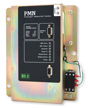
The Modbus Plus address of the PMN is set by means of a pair of rotary switches on the front of the unit. The RS-485 serial port is self configuring. No other
configuration is required.
Mounting The PMN can be mounted two ways.
The PMN is designed to attach to the back of a POWERLOGIC Circuit Monitor, similar to the IOM can. It is normally powered by connecting the pigtail power leads to the 110/220 VAC terminals on the Circuit Monitor.
When a Circuit Monitor has I/O attached use the PMN-SA.
The PMN-SA is a stand-alone version which includes a panel-mount mounting plate. It is powered by 90-276 VAC or 125-350 VDC through a 3-position terminal block. The
serial data connection is made through a DB9 connector on the front of the PMN-SA. This connector has the same pinout as a SY/MAX port and provides slide-locks for the
SY/MAX cable. Use a Niobrara DC7 to connect the PMN-SA to the circuit monitor.
Ordering Information
The PMN is available as:
* PMN with Pigtail RS-422/RS-485 port, 9-pin Modbus Plus port.
* PMN-SA with SY/MAX RS-422/RS-485 port, 9-pin Modbus Plus port, mounting plate.
Related Equipment
The PMN has the following equipment available:
* DC7 9-pin SY/MAX differential cable, connect a PMN-SA to a circuit monitor.
Specifications
Warranty / Manual: The PMN is furnished with a user manual on cd and carries a one year warranty from the date of shipment. During the warranty period, free firmware upgrades are available. See Niobrara's Standard Terms and Conditions of Sale for additional warranty information.
Dimensions: 6.2" wide by 9.2" high by 1.6" deep (158 x 234 x 41 mm); 2 pounds (900g) net weight. Heavy duty steel case with brushed chromate finish.
Mounting Plate: 7.35" wide by 9.3" high.
Power Requirements: 90-276 VAC (47-63 Hz) or 125-350 VDC; 6 watts.
PMN Power Connector: 3-wire pigtail with spade connectors on conductors. Attaches to Circuit Monitor power.
PMN-SA Power Connector: 3-position screw terminal.
Serial Port Modes: PNIM Master and/or Modbus RTU Master protocol. Baud rate is automatically configured.
PMN Serial Port: RS-422/RS-485 4-wire pigtail with spade connectors on conductors. PowerLogic color code.
PMN-SA Serial Port: 9-pin female D-subminiature connector with slide locks. SY/MAX pinout.
Modbus Plus Port: 9-pin D-subminiature female connector w/screw lock; standard Modbus Plus pinout. Address set with two front panel mounted rotary switches.
Indicators: LED indicators for Power, Module Active and Error, Modbus Plus Active and Error, Serial Transmit and Receive; seven total indicators.