Home
Products
Cables
DIN Rail Products
Modicon Products
M580
Quantum
Compact
Momentum
MST
Cutsheet
MSTD-101
MSTD-102
MSTD-103
MSTD-108
MSTD-201
MSTD-203
MSTD-205
MSTD-206
MSTD-207
MSTD-301
MSTD-303
MSTD-304
MSTS-101
MSTS-102
MSTS-201
MSTS-203
MST Cross
Reference
MLWF
MUCM
FAQs
Square D Products
Download Area
Price List
Application Notes
Support
NR&D Distributors
Momentum™
Serial Communications
Adapter
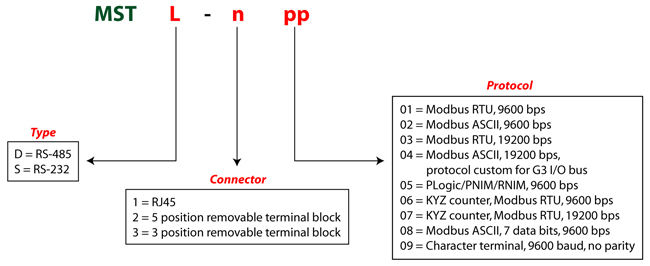
Niobrara’s MST family of products are optically isolated serial communications adapters for TSX Momentum® I/O. Two variants are available; the MSTD is equipped with an RS-485 port for multidrop applications, and the MSTS utilizes an RS-232 port for point-to-point communications. Each MST variant can have multiple versions, designated by a three digit suffix; e.g. MSTD-101.
Each MST version has a fixed baud rate and protocol.
The Modbus versions of the MST mimic the registers of Modicon’s Ethernet Communication Adapter with additional registers and capabilities. For example, the MST makes it possible to read the state of the outputs (4x registers 101 through 132). The MST also contains a configurable watchdog timer to zero the output registers whenever communication is lost.
MST applications
- Add Momentum I/O to a Modbus serial network.
- Connect to a modem for dial-up I/O
- Put Momentum I/O on a Modbus or RNIM radio network
- Put Momentum I/O on a POWERLOGIC® or POWERLINK® network.
- Put Momentum I/O on a Modbus power management system
- Provide a serial interface for motor drives
-
Build a Serial to Seriplex™ bridge.
MST Benefits
- No programming required
- Ability to read outputs
- Watchdog operates on all 32 output registers
- Add multiple I/O to Ethernet when out of IP addresses (requires a bridge)
-
Configurable default output condition
Momentum Compatibility
The MST supports any Momentum I/O base, auto-detects the base ID code and reports this in 4x register 204. The MST does not support any Option Adapters.Power
The Momentum base powers the MST through the base/tophat connector. The MST power consumption is 0.25 watts, far less than the 5-watt minimum power that Modicon specifies Momentum bases provide. Devices powered by the +5 Volts on the RS-232 connector must not draw in excess of 100mA since this may exceed the power output of the Momentum base.Configuration
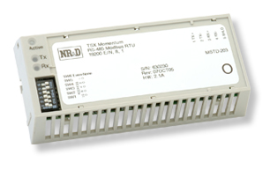
The address and parity of the module is configured via a six-position DIP-switch on top of the module. Valid addresses are 1 through 31. Power-up and default output conditions are user configurable by setting the outputs and writing the default-save register. This feature permits automatic base configuration on power-up.The communication-loss watchdog timer is configured via Modbus write. The default timer value is 30 seconds. The default output condition is all outputs off. Future MST versions may have other configuration options.
LEDs
The MST has three LEDs. The green LED indicates the module is powered and configured (on steady) or powered but not configured (flashing slowly). The amber LEDs indicate when the module is transmitting (TX on) and receiving (RX on).Statistics
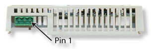
There are statistics registers to indicate tophat/base communication health, last I/O module error, and I/O module communication error count.Pinouts
The following tables illustrate the connector pinouts for each MST variant.RJ45 RS-232 Port Pin Function 1 +5VDC (100 mA max. output) 2 No Connection 3 TX (out) 4 RX (in) 5 Signal GND 6 RTS (out) 7 CTS (in) 8 Chassis GND