
Home
Products
Cables
DIN Rail Products
Modicon Products
M580
Quantum
QASI
QRIO
Manual
Cutsheet
PowerPoint
Software
Example Video
QUCM
QSPXM
QXBP
FAQs
Compact
Momentum
Square D Products
Download Area
Price List
Application Notes
Support
NR&D Distributors
Quantum Remote I/O Scanner
Allen-Bradley® Universal Remote I/O Scanner
Download the WMV version
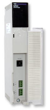
Description The QRIO is a scanner card for controlling devices on an Allen-Bradley Universal Remote I/O (RIO) network from a Schneider Electric Quantum PLC. It is ideal for customers that have an installed Universal Remote I/O network and want to upgrade to a Quantum PLC without changing out all of their remote I/O. Also, upgrading a PLC-2, PLC-5, or SLC system to a Quantum is now as easy as replacing the A-B processor with a 1771-ASB or 1741-ASB module to convert the A-B rack to Univeral Remote I/O.
The QRIO is a Quantum form factor, single-width module with two RIO ports and an RS-232 serial port on the front. The QRIO is a Quantum PLC option module and must be used in local racks. It is compatible with all Quantum PLC programming packages that support the NOE 771 00 Ethernet Option module, including Unity Pro, Concept, Modsoft and ProWORX.
The QRIO-002 supports Hot Standby
The QRIO may operate in a Quantum Hot Standby PLC system.
A QRIO is installed in each of the two CPU PLC racks enabling the Hot Standby system to control Allen-Bradley Universal Remote I/O.
The QRIO units collectively control up to two separate RIO networks, coordinating during a Hot Standby changeover to smoothly hand off control of the attached I/O.
This firmware upgrade is compatible with all hardware revisions of the QRIO, but additional cabling is required to allow the QRIOs direct communication with one another in Hot Standby installations.
Applications The QRIO supports three different mechanisms for communicating with RIO devices: Discrete I/O, Block Transfer I/O, and Block Transfer Messaging. The QRIO can use any or all of the mechanisms, depending upon the capabilities of the remote devices.
Discrete I/O is updated via the PLC's I/O scanning table. Block Transfer I/O and Block Transfer Messaging are accomplished using the Quantum's MSTR instructions. This is similar to Allen-Bradley's mechanism for accessing devices that use these message types.
When using the I/O scanning table, data from the Discrete I/O devices are placed into the PLC's 4x, 3x, 1x, or 0x memory. The Discrete I/O devices are written with data coming directly from the Quantum's PLC registers.
The QRIO is configured via the PLC programming software; no new configuration software or MDC files are required. When configuring the QRIO, the user selects the NOE 771 00 Ethernet Option module for the QRIO's module type. The baud rates of the serial ports are configured in the IP address area of the module configuration.
The I/O scanner table is also configured and stored in the PLC.
Since the entire configuration of the QRIO is stored in the PLC, a QRIO can be replaced without requiring a laptop to configure the new one.
Remote I/O Ports The QRIO has two independent RIO ports. Each port will support up to 32 RIO logical devices, so each QRIO can support up to 64 RIO devices on two networks. The QRIO scans the Remote I/O network under the control of the PLC, but it is important to note that Remote I/O scans and PLC scans are asynchronous.
The RIO ports use removable screw-terminal connectors to allow for fast module changes. The baud rates of the two ports are independently configurable.
Serial Port Flash memory allows the firmware in the QRIO to be updated in the field. The serial port of the QRIO is an RS-232 port with an RJ45 connector. It has the same pinout as Modicon's Compact, Micro and Momentum PLCs. The programming cable for the listed PLCs can be used when upgrading the QRIO firmware, or purchase a Niobrara MM1 cable. A firmware load/run switch is located on the back of the module.
Ordering Information
The QRIO is available as:
* QRIO-002 with 2 Remote I/O Ports.
QRIO Accessories:
| MM1 | RS-232 cable for loading firmware into QRIO. Also used with the MM3 cable for Hot Standby operation. |
| MM3 | RS-232 cable used with the MM1 cable for Hot Standby operation. |
Specifications
Warranty / Manual: The QRIO is furnished with a user manual on cd and carries a one year warranty from the date of shipment. During the warranty period, free firmware upgrades are available. See Niobrara's Standard Terms and Conditions of Sale for additional warranty information.
Dimensions: Standard Quantum module. 1.59" wide by 9.84" tall by 4.09" deep (40 x 250 x104 mm). Approximately 12 oz. (340 g.) net. All connectors and indicators are front-mounted except the Quantum bus card edge connector on the back.
Power Requirements: From Quantum bus; 5 VDC, 500mA max (400mA typical).
Operating Conditions: 0 to 60 degrees C; humidity up to 90% noncondensing; pressure altitude -200 to +10,000 feet MSL.
Serial Port: RS-232 serial data port. RJ45 female connector, Modicon Micro pinout.
Remote I/O Ports: Two 3-position removable connectors with screw terminals. 57.6, 115.2 or 230.4 Kbaud, software configurable.
Indicators: LED indicators for Module Active, Ready, Run, and Fault; Network Comms; and serial port TX and RX.